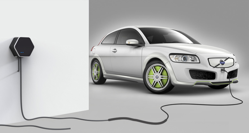
This post is part of a series about Prism, an open charging station
Before going on with the electronics, I’d like to write a bit about the most painful and stressful part of building a product: the enclosure.
Continue reading Enclosure hell
This post is part of a series about Prism, an open charging station
Before going on with the electronics, I’d like to write a bit about the most painful and stressful part of building a product: the enclosure.
Continue reading Enclosure hell
This post is part of a series about Prism, an open charging station
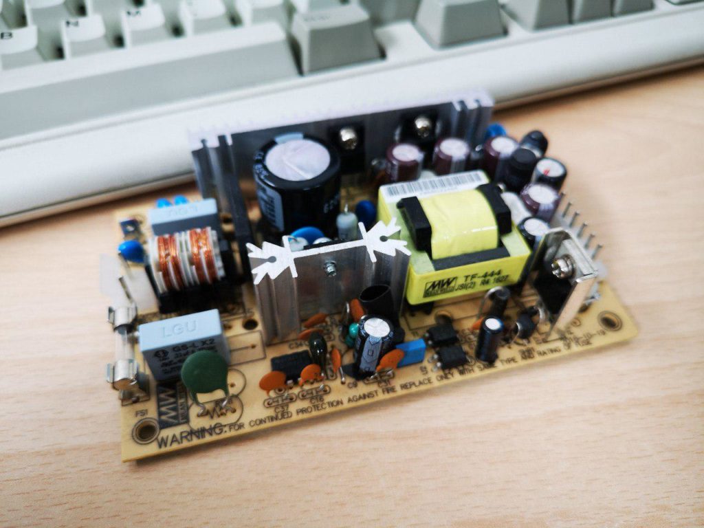
Supplying power to everything is not as easy as it may seem. We need several voltages to power all the components, here’s the budget:
Continue reading Power!This post is part of a series about Prism, an open charging station
Of course the first thing that comes to the average makers mind when they want to add smart connectivity to something is the venerable Raspberry PI. These boards are great, but almost impossible to find in quantity and definitely impossible to buy at the advertised price if you live outside USA. The only Raspberry I could consider for size and availability is the CM version, but I’d have to add WiFi and Ethernet to the already high price of the board. Finally, they’re way overpowered for my purpose. What I’m looking for is the sweet spot between a Raspberry PI and an ESP32 in terms of size, price and features.
This post is part of a series about Prism, an open charging station
The EVSE decides what’s the maximum current a car can draw; this is because only the EVSE knows how it’s installed. If it’s a portable EVSE, the Pilot signal will limit the charge to the AC plug or cable rating. If it’s a wallbox, the installer should have configured it according to the mains wiring specifications. The car should comply with that limit, and the EVSE should disconnect the car if it exceeds it, to prevent fires and avoid tripping the circuit breaker.
This post is part of a series about Prism, an open charging station
The basic building blocks of an EVSE are pretty standard.
We start, of course, with a power supply for the low voltage circuitry. While this may seem a very simple and straightforward piece to solve, there are a lot of variables to consider: we need ±12V at 12mA for the pilot signal, 5V and 3.3V for the logic, and an isolated 3.3V for the high voltage measurement circuit, with signal isolation too. We will think about this after testing the other components to have a clearer idea of all the requirements.